Customer
Project: Project Name
![]()
Hyster Robotics
Customer
Project: Project Name
![]()
Hyster Robotics
Application Requirement overview
General Technical Recommendations
Distribution of Supplies & Services
Application GENERAL Description
![]()
![]() The
data and information presented in this document is intended for Hyster
Authorised Dealers, Service Representatives and selected customers. Some or
all of the data, concepts, text and images within this document may be
commercially and technically sensitive and as such should be distributed with
the utmost care and caution.
The
data and information presented in this document is intended for Hyster
Authorised Dealers, Service Representatives and selected customers. Some or
all of the data, concepts, text and images within this document may be
commercially and technically sensitive and as such should be distributed with
the utmost care and caution.
This quote describes the solution to the request by HYG for the installation of automated vehicles at the customer facility.
This quote is version controlled once agreed by both parties – any requested changes to be managed by the change process described in the Terms and Conditions.
A simulation may be used to support some of the assumptions made in this document – this is a computer model of the application and the vehicles operation within it. These simulations can be been made available to the customer.
|
Version |
Date |
Comment |
|
<<version>> |
<<date>> |
<<comment>> |
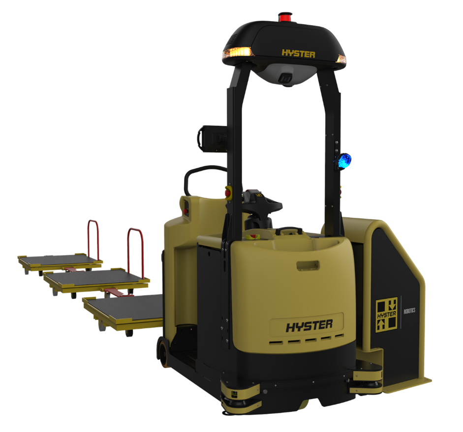
Hyster robotics is a system that can be installed at a customer site to provide automated operation. It utilises the standard product produced by HYG with all the advantages of a proven solution as the base for the automated vehicle. The additional parts fitted provide a highly productive automated solution for multiple applications. All Hyster Robotic trucks can be operated in both manual and automated modes. The robotics system also incorporates a cloud based traffic manager which manages the AGV’s interface to the site including all of the logistics information, vehicle management, interfaces to Warehouse management systems or ‘communication boxes’ and provides an interface for the customer to visualise the operation and status of the system. A site connector is also required, this is a small computer housed on the customer’s premises. Communication boxes can be installed, and these provide specific inputs to support the operation.
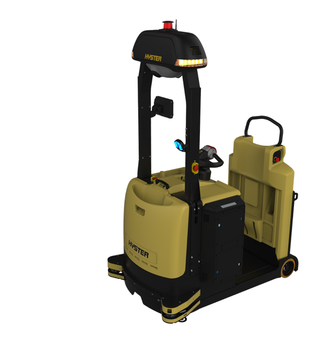
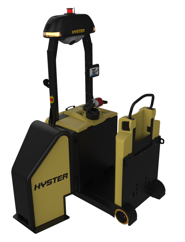
Model LO7.0T
Load Type Trailers
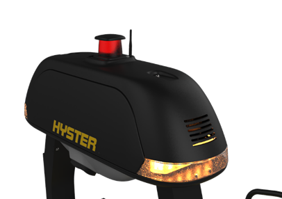
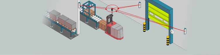
Navigation laser mounted at 2400mm,
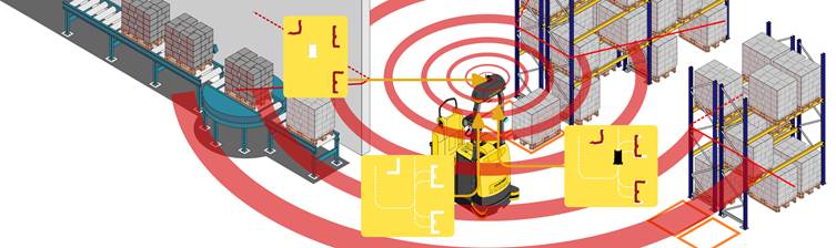
The navigation system does not require any infrastructure change at the customer site. The Lidar is mounted in an elevated position to enable a greater number of fixed objects to be recognised.
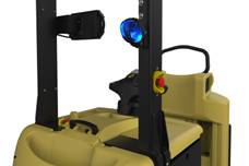
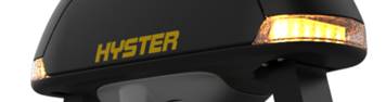
Pedestrian aware light will project a blue beam onto the floor in front of the truck.
 Curtain camera
will detect, objects, drop offs and for example if the forks have been left
raised on a manually operated truck.
Curtain camera
will detect, objects, drop offs and for example if the forks have been left
raised on a manually operated truck.
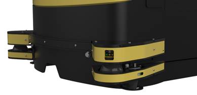 Personal
protection utilising laser technology. The laser enables the vehicle to automatically
slowdown and/or stop depending on the distance from the obstruction to the
truck.
Personal
protection utilising laser technology. The laser enables the vehicle to automatically
slowdown and/or stop depending on the distance from the obstruction to the
truck.

Interactive Touch Screen display allows user interface, provides information to enable user to change operating mode from a manual to an automatic state, shows current task information, and status.
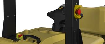
Flashing lights on the machine when travelling in automatic mode, and e-stop buttons.
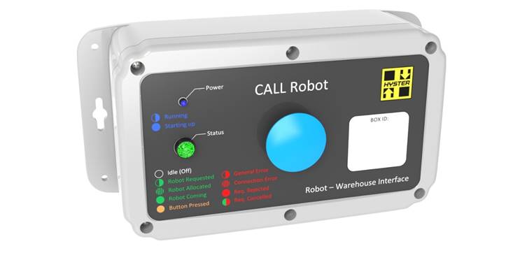
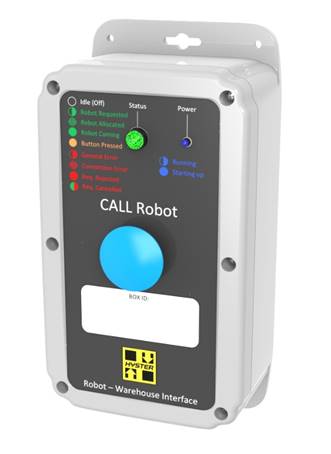
Communication box
The communication box will be highly configurable enabling multiple types of input including button press, sensors and cameras. It will include 6 inputs; will have Wi-Fi and Ethernet interfaces and an optional POE.
Power & Network Access For Communication boxes
The customer should provide a 220V AC power supply and a 10/100 BaseT/TX Ethernet connection (providing access to the network on which the traffic manager will be installed) in each location where the boxes will be installed. The customer will also ensure the feasibility of running cables from the Communication box to the sensors/elements with which it interfaces.
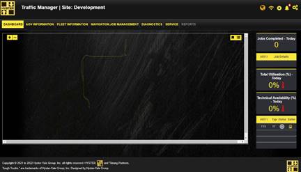 Traffic Manager
A Traffic manager will be provided. This is accessible using a standard computer via xxxxxxx.com. Passwords for both admin and user profiles will be made available. The TMP is cloud based system that manages the AGVs on the site including:
· Vehicle management
o Truck identification
o Truck availability
· Site management
o Logistics information – what goes where
o Specific requirements within a site – traffic free areas, etc.
o Interaction with site infrastructure – doorways, fire alarms etc.
· Job management
o Planning the routes of the vehicles
o Congestion management
· Interface to the warehouse management system (receiving job information)
o SAP or similar
o interface switches or buttons on site
· other interfaces
o interface to the customer Wi-Fi
o interface to data lake
· Data management
o Capture performance of the vehicles
o Capture performance of the operation
· Provides a user interface
o Visualise the operation
o Map view
o Performance view
o Effect the operation
§ Cancel a job
§ Move a truck to manual operation
§ Access management
o Commissioning / set-up
§ Supervisor
§ Operator
· Visualise KPIs
o Per truck
o Per fleet
o Create reports
o ![]()
![]() Simple Diagnostics
Simple Diagnostics
The Robotic system requires a site connector; This is a small server which needs to be installed at the customer site. This provides the interface to the company systems and to the communication boxes.
Hyter robotics recommends Lenovo SE30 for connection requirements please see IT integration section
The site connector may also be supplied as a VM which can be installed on a customer machine, minimum requirements
· 1
· 2
· 3
![]()
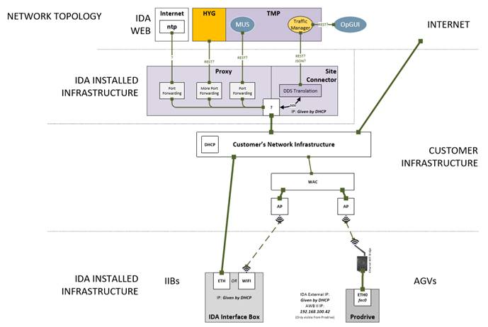
![]() Netwrok topology (to be updated refer to Hyster robotics – remove Ida
and prodrive ref.)
Netwrok topology (to be updated refer to Hyster robotics – remove Ida
and prodrive ref.)
WiFi
The Hyster Robotics system requires Wi-Fi in order to operate both in terms of data rates and coverage the minimum requirement for the Wi-Fi which is outlined below.
If the customer is unsure of their Wi-Fi suitability HYG can carry out a survey and create a report of suitability and suggested changes. It is the customers responsibility to ensure the Wi-Fi is correctly set-up and has adequate performance
Wi-Fi set-up requirements:
· Hyster Robotics will require a dedicated SSID
· Use of 5Ghz band only not 2.4Ghz
· 802.11r to be enabled – 802.11b to be disabled
· Do not drop BUM traffic (Broadcast / Unknown Unicast / Multicast)
· Avoid channel overlap
· Avoid 80MHz band widths. Use 20MHz or maximum 40MHz
Wi-Fi Performance requirements
· Beacon Availability 100%
· Radio Attach Success Rate 100%
· DHCP Success Rate 100%
· DHCP Time < 10 Seconds
· Ping Success Rate 100%
· VoIP MOS Downlink > 1.25
· VoIP MOS Uplink > 1.75
· CRC Error Rate < 40%
Other best practice recommendations
· Verify access point locations, use directional antennas, when possible, with correct aiming
· Unhide hidden SSIDs
· Limit number if SSIDs (max 3-4) – Every SSID sends its own beacon typically every 100ms therefore more SSIDs, more management traffic utilization
· Define limited range for automatic transmit power control (if used)
· Allow automatic channel changes only e.g., every 12 or 24h max
· Verify coverage area with site survey when shelves are fully stocked
· Understand device client capabilities
· Optimize roaming e.g. with power control (15-20% coverage overlap with -67dBm signal), supported bit rates, roaming sensitivity, 802.11k/r if supported
Port Specification
· ???
Standard lead acid and Li-ion batteries can be used. The Robotic system can monitor the battery state of change and return the truck to the charging area when needed for a battery charge or a battery swap.
![]()
![]() Auto
charging can be supplied. Please contact Hyster for more information.
Auto
charging can be supplied. Please contact Hyster for more information.
Prior to installation and operation it is important for our customer to understand and mitigate the risks associated with operation of automated guided vehicles. A guide is available that highlights areas to be aware of. HYG will support our customer in the understanding and mitigation of these risks. (see supporting document)
In order to meet the flows requested in the application the following requirements of the application must be met:
· The Routes that the AGV take must be kept clear of obstacles such as stillages, parked trucks and materials.
· Manually driven vehicles must give priority to AGVs at junctions and in narrow aisles.
· AGVs will be given priority at pedestrian crossings (they will slow but continue to drive).
· Provision must be made to ensure manually driven vehicles with wide loads do not block the aisle being used by the AGV.
· The stillages / loads need to be placed within 30mm of the expected position.
· One placed the stillages should not be moved.
· Areas which have been dedicated for the AGV to interact with such as charge areas, park areas, stillage locations must be kept clear at all times apart from the expected loads or items.
· Manual interaction such as hitching trailers must be done in a timely manner.
![]()
![]() The
installation of the Hyster Robotics solutions firstly requires any site
specific infrastructure to be in place such as communication boxes and sensors
/ triggers and the site connector. The AGV(s) will arrive on site and installation
can start. This will be done initially via the TMP to configure the system and add
all of the trucks and communication boxes to the application. The truck will
undergo some initial testing on site to ensure operation. A mapping run will
then take place, this involves manually driving the truck in the applicable
locations. This creates a map which the truck then uses during operation. This
map is uploaded to the traffic manager along with logistics information, key
interaction areas, communication box positions, charging positions etc. Logic
for communication box operation is added along with route definition (note some
of this can be done in advance via the simulation). There would then be test
runs to ensure the correct operation of the system.
The
installation of the Hyster Robotics solutions firstly requires any site
specific infrastructure to be in place such as communication boxes and sensors
/ triggers and the site connector. The AGV(s) will arrive on site and installation
can start. This will be done initially via the TMP to configure the system and add
all of the trucks and communication boxes to the application. The truck will
undergo some initial testing on site to ensure operation. A mapping run will
then take place, this involves manually driving the truck in the applicable
locations. This creates a map which the truck then uses during operation. This
map is uploaded to the traffic manager along with logistics information, key
interaction areas, communication box positions, charging positions etc. Logic
for communication box operation is added along with route definition (note some
of this can be done in advance via the simulation). There would then be test
runs to ensure the correct operation of the system.
Following the order the truck availability is usually 16 weeks. The target installation after truck delivery is 1-6 weeks, the exact duration depends on the complexity of the solution and the number of Robotic Forklift Trucks that are required. To manage this process, a Project Manager will be assigned to ensure the smooth progress of the activities, from order to acceptance. The following activities take place following an order:
· The AGVs are ordered on the factory and associated equipment is ordered.
· Pre-work at the customer site.
· Delivery of the vehicles.
· System configuration.
· Mapping the environment and planning of the routes.
· Set up and linkage into traffic management.
· Safety Tests.
· Functional testing - adjustment and fine-tuning of the routes and operation.
· Operation running – AGV carrying out the task fully integrated as expected.
· Customer acceptance.
· Monitoring and update- to promote smooth operation. This is usually around 3 months.
Above text to be reviewed and small plan to be added
Dependability and Serviceability are two major pillars of Hyster design. We try to put as much effort into designing our support structures and processes as we do our forklift trucks. Our Robotic Forklift Trucks are based on our manual forklift range and come with all the intelligent design features that enable easy and efficient maintenance throughout the equipment lifetime.
The first-line of service support, the trained technicians of the Authorised Hyster Dealer network, are all fully trained not only on the base forklift truck but also the Robotic Forklift Truck systems. This training enables the technician to maintain, diagnose and repair common problems quickly and efficiently.
If the technician encounters a problem that they cannot solve in the field by themselves, they can rely on Hyster's own Field Service and Factory Service teams. These teams themselves have in-depth training and knowledge of the Robotic Forklift Truck systems and support infrastructure to be able to provide timely telephone, email & in-person support.
Hyster Field and Factory Service teams via a dedicated support helpdesk. This facility is co-located with the Robotic Forklift Truck development and production centre and can provide very deep knowledge and support, in the event that this is required.
![]()
![]() In the event that a problem
makes it this far, we will apply the very engineers who design our Robotic
Forklift Trucks to the issue.
In the event that a problem
makes it this far, we will apply the very engineers who design our Robotic
Forklift Trucks to the issue.
The European standard NF EN 1525:1997 requires the client to fulfil the conditions below.
The client must maintain the floor in operating conditions that comply with Hyster Installation and Technical terms of use. In addition, the client must agree not to allow a truck to operate in the event of liquids, dust, ice, etc. being present on its path to avoid the risk of the truck skidding, particularly in the event the emergency brake is used. Finally, the client agrees to ensure that all equipment that comes into contact with the robots is in good working order.
A minimum safety clearance distance of 500 mm in width and 2100 mm in height must be maintained on both sides of the widest part of the truck / load combined. It is the client's responsibility to maintain the guide path (the route to be followed when on automatic setting) in accordance with European standard ISO 3691-4 : 2020
![]()
![]() Zones that are judged to be
hazardous, whether by the client or the supplier, must be clearly identified
and must feature specific displays forbidding the presence of unauthorised
personnel. If maintenance work is to take place in this zone, only authorised
personnel may enter. 'Authorised personnel' refers to anyone who has been
clearly appointed by the supplier, is adequately trained and qualified, and who
has the necessary instructions to successfully carry out the task.
Zones that are judged to be
hazardous, whether by the client or the supplier, must be clearly identified
and must feature specific displays forbidding the presence of unauthorised
personnel. If maintenance work is to take place in this zone, only authorised
personnel may enter. 'Authorised personnel' refers to anyone who has been
clearly appointed by the supplier, is adequately trained and qualified, and who
has the necessary instructions to successfully carry out the task.
|
General Services |
Hyster |
Client |
|
|
|
Signing the project specifications document. |
X |
X |
|
|
|
Any administrative procedure for obtaining driving permits for staff employed by Hyster with a description of the procedure and list of contact persons. |
|
X |
|
|
|
Supply of equipment listed in the offer. |
X |
|
|
|
|
Factory testing of Hyster equipment (FAT). |
X |
|
|
|
|
Monitoring of Hyster sub-contracting |
X |
|
|
|
|
Monitoring of Client sub-contracting. |
|
X |
|
|
|
Transportation of equipment to the site and related insurance. |
X |
|
|
|
|
Definition of the circuit and the load transfer points of the solution. |
X |
X |
|
|
|
Provision of site plans and information on the installations’ surrounding environment. |
|
X |
|
|
|
Provision of CE certifications for the equipment and the installation. |
X |
|
|
|
|
Provision of user manuals for the Equipment and solution. |
X |
|
|
|
|
Convening of the site’s Committee for Heath, Safety and Working Conditions and staff representatives. |
|
X |
|
|
|
Presentation of the solution to representative organisations (on request) |
X |
X |
|
|
|
On-site storage of equipment. |
|
X |
|
|
|
Installation of battery chargers. |
|
X |
|
|
|
Installation of communication box and sensors. |
|
X |
|
|
|
Provision of an office with Internet access. |
|
X |
|
|
|
Provision of robot development zones for configuring the solution. |
|
X |
|
|
|
Performing on-site equipment safety tests. |
X |
X |
|
|
|
Performing operational tests before deployment. |
X |
X |
|
|
|
Supervised deployment (duration to be confirmed). |
X |
X |
|
|
|
Provision of user training on the solution. |
X |
X |
|
|
|
Safety training for all staff. |
X |
X |
|
|
|
Site and solution risk assessment performed. |
X |
X |
|
|
|
Development of the site in accordance with the results of the risk assessment (floor markings, signage, etc.) |
|
X |
|
|
Power supply to and wiring of protected outputs from Hyster equipment. |
|
X |
|
|
Power supply to Hyster equipment (at the necessary voltage). |
|
X |
|
|
Provision of network access to communication box. |
|
X |
|
|
Provision of a dedicated PC or virtual machine on a dedicated server for the installation of the supervision software. |
|
X |
|
|
Supply of logic signals at the communication level. Electrical consignment. |
|
X |
|
ROBOTIC trucks are fitted with a protection system, this feature ensures the vehicle will slow down and stop in the event of an object being in the path of the vehicle.
There are 2 versions available
- 360 – all round protection recommended (protection in all directions)
- 270 – protection in the direction of travel (all manoeuvres in reverse will be at very slow speed 0.3m/s)

The Protection system is orientated towards direction of travel, there are 3 fields update picture
· Warning field (W) - size depends on speed– truck will slow down if an object is detected
· Protection field (P) – size depends on field truck will stop if an object is detected
· Escape field (E) 500mm – the truck will not start if there is an object in this field
· Note when handling a load the protection fields can be ‘muted’ to enable load interaction
To ensure the safe operation of the Hyster solution (robot and its system), all robots will undergo a braking test at the client's site in the most restrictive and adverse conditions to ensure the personnel protection zone works in accordance with the most adverse conditions.
The Solution is delivered with complete documentation:
· Installation documentation: routes, safety areas, signage, user training, solution user manual, risk assessment results.
· For each robot, the instruction manual for the robot.
The robots have been designed for inside operation only, Environmental restrictions below:
|
Operating areas |
Indoor |
|
Operating temperature |
from +0°C to +40°C (no "cold storage" application) |
|
Maximum temperature |
+40°C during a maximum of 1 hour |
|
Average temperature during 24 h |
35°C max. |
|
Relative Humidity |
45-90 % (at +20°C) without condensation |
|
Maximum temperature change |
±5 °C per hour |
|
Chemical products, aggressive gases |
none (or negligible concentrations) |
|
Admissible dust quantities |
concentration permitting the normal operation of technical systems – contact Hyster Robotics for further clarification |
|
Hazard zones |
Our components cannot be used in hazard zones / explosives (ATEX) |
|
Mechanical vibrations |
the vibrations must not interfere with the stability of the fixed cabinets and switchboards or the vehicles |
Thanks to our high precision mapping navigation, the vehicles always follow predefined travel paths. So as to avoid creation or passage on ruts, the operational surface should not have plastic deformations (asphalt and tar are forbidden). The surface must be permanently dry. The quality of all circuit paths must be in compliance with the technical conditions of the robot. These conditions must be respected and if required, corrected by the customer. Hyster cannot neither test nor approve the surface quality before installation. If in doubt, there are independent certification bodies who propose floor testing to discover the suitability and validation for the standards defined in this document.
The floor for use by our robots must as a minimum comply with the required standards of the supplier of the original truck.
Note: The use of our robots may lead to premature wear of floors.
Compressive resistance
Static - 6 to 8 N / mm2; dynamic - 12 to 16 N / mm2. The definitively required resistance will be validated once all the technical details are known. In the series of standards DIN EN 1991, "Actions on structures", we recommend in particular chapter 1-1: 2010-12 and DIN EN 1991-1-1/NA:2010-12.
Friction
µ ≥ 0.6 (wheel material: Urethane elastomer or similar)
![]()
![]() Floor surface resistance
Floor surface resistance
The customer's floor must comply with references VDI 2510-1 and VDI 4452: RE ≤ 106 Ω, Electrostatic Conducting floor – ECF, measurements in compliance with EN 1081. In some circumstances, it is possible to work with higher resistance values. This should be the object of a case-by-case evaluation.
To use the robots, the floor must be flat and level. The tolerances of the travel paths should comply with DIN Standard 18202:2013, "Tolerances in building construction", Table 3, Line 3. For loading stations or load transfer (pick-up and/or drop-off), the requirements will be higher. In particular for a load transfer higher than 1 m from the floor. In this case, the floor must comply with line 4. When the pallets are not in compliance with EN Standard 13698-1:2003, other standards may be applied.
The tolerance values indicated above are zones of tolerance, that is to say measurement points at a given distance: par example at a distance of 1 m, a tolerance zone of 3 to 4 mm is recommended. The absolute tolerance value is from ± 1.5 to ± 2 mm. In transfer stations, the floor should be sufficiently flat to guarantee proper positioning and satisfy the requirements of the load transfer
Expansions joints and holes must be specially treated so as to avoid shocks on the loads and on the vehicle. Expansion joints and holes wider than 5 mm or of height difference of more than 3 mm should be reworked using adapted "armouring".
During installation of our robots, a minimum distance of about 200 mm should be left from this type of obstacle, so as to ensure sufficient weight distribution.
The travel paths should be permanently dry. The frictional and static dissipation properties should not be deteriorated by chemical products, fluids or any other type of contamination or modification of the floor surface. The frictional properties are very important, in particular for the braking distance of the vehicles.
<<Location description, including town/city & country. Include a site overview (satellite image or architectural site plan.>>
<<Include interior site plan/drawing of the working area. Measure and state the working area size, for mapping purposes.>>
<<Number of shifts per day and the working days per week.>>
<<List the environmental data given and whether this is stated by the customer/dealer or gained from a physical visit. Include floor condition, temperature, humidity, dust & lighting.>>
<<Summary statement of customer’s requested flows. Include if present an image of their flow diagram.>>
<<Details of the loads required to be moved. Include weights and indicate the fork entry side. Include drawings and/or pictures if possible.>>
<<Show details of any automatic doors or doors that are likely required to be controlled via COMBOX here.>>
In all cases, a minimum of 2.5 metres clear space is required overhead any areas where the vehicle will operate.
In all cases, the detection field coverage of the robot will extend a minimum of 100 mm each side of the widest point of the vehicle and load:
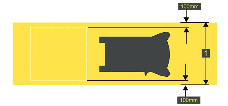
In the case of this application, we consider we are handling 1,000 mm width trailers. The minimum reserved width for a driveway (dimension ‘A’) would be 1,200 mm. Where possible, we would advise a reserved width wider than this, for operating tolerance purposes. Additionally, towed trailers will tend to cut across the corner when a turn is made by the robot. This must be accounted for in any circuit developed. The issue will become more pronounced when there are more trailers in a train but can be somewhat alleviated by the use of linked axles and steering mechanisms.
In all cases, the ideal clearance is 500 mm, measured from the widest part of the robot or carried load.
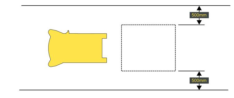
This is the minimum case. We aim to provide this clearance as measured from the detection fields. This increases the effective clearance to 600 mm per side.
500 mm clearance is the minimum case clearance for any defined pedestrian walkways.
![]()
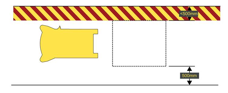
It isn’t always possible to maintain 500 mm clearance on both sides of the vehicle. In these cases, 500 mm is acceptable on one side. In these cases of reduced clearance, the area should be marked as a ‘Hazard Zone’.
This section aims to define the contractual success criteria.
This section will be used by the Hyster project management team to lead the commercial and technical discussions regarding the system performance.
Unburdened Throughput is a 5 hour performance test. Due to the ramp up of the system, when starting the first 2 hours will not be taken into account in the performance calculation.
During this test, Hyster is committed to ensure a 100% unburdened throughput.
If the system does not meet the performance requirement, a report stating the reasons shall be generated. Hyster and or the Customer will address all known issues and repeat the performance test within the ramp up agreed timing.
If the system is underperforming due to reasons beyond the control of Hyster (Customer related reasons: lack of missions, operator interference) then the performance test shall be considered successful and allow handover. In this case, if the Customer requires an extra performance test, such a test may be quoted and planned as a change request.
The Technology Availability ratio aims to calculate the percentage of time the robot is productive compared to the sum of productive time and error time due to a technical error as documented in VDI 3423.
Test duration will be 8 hours. Due to the ramp up of the system when starting, the first two hours of the test will not be taken into account in the performance calculation.
The use of the installation and the coordination of the material flows are done by the customer in coordination with Hyster.
The performance test will be run under “live” conditions with all equipment speeds and parameters set for nominal operating conditions.
During this test, Hyster is committed to ensure a 98% Technology Availability.
![]()
|
NAME |
LOAD TYPE |
WIDTH |
LENGTH |
MIN WEIGHT |
MAX WEIGHT |
|
Trailer |
Trailer |
600 |
800 |
50 |
500 |
|
NAME |
STATION TYPE |
QUANTITY |
|
Supermarket Kitting |
Tow Tractor Station |
1 |
|
Kit 1 |
Tow Tractor Station |
1 |
|
Kit 2 |
Tow Tractor Station |
1 |
|
Empty |
Tow Tractor Station |
1 |
|
NAME |
PICK FROM |
LOAD |
DROP TO |
DISTANCE |
TRIPS |
WAIT TIME |
TRIGGER |
|
Kit 1 |
Super Market |
Trailer1 |
Kit 1 |
64 |
1 |
120 |
Push Button |
|
Kit 1 return |
Kit 1 |
Trailer1 |
Super Market |
140 |
1 |
120 |
HMI |
|
Kit 2 |
Super Market |
Trailer1 |
Kit 2 |
50 |
1 |
120 |
Push Button |
|
Kit 2 return |
Kit 2 |
Trailer1 |
Super Market |
110 |
1 |
120 |
HMI |
|
Empty |
Super Market |
Trailer1 |
Empty |
110 |
1 |
120 |
Push Button |
|
Empty return |
Empty |
Trailer1 |
Super Market |
50 |
1 |
120 |
HMI |
Based on the above numbers the calculated number of trucks required would be approximately 0.45
The number of communication boxes required have been identified as;
![]()
![]() 3 – Push
Button Call Boxes,
3 – Push
Button Call Boxes,
1 – IO for fire alarm integration
|
Item |
Quantity |
Total Price (EUR) |
|
Robot |
1 |
- |
|
|
|
|
|
Item |
Quantity |
Total Price (EUR) |
|
Battery |
1 |
|
|
|
|
|
|
Item |
Price (EUR) |
|
|
Free of charge |
|
|
|
|
|
|
|
Item |
Quantity |
Total Price (EUR) |
|
Communication box Push Button |
3 |
|
|
Communication box IO |
1 |
|
|
Site Connector |
|
|
|
|
|
|
|
Item |
Price (EUR) |
|
Robot Manager |
|
|
Project Management |
|
|
Installation |
|
|
Mapping |
|
|
Safety certification & documentation |
|
|
WMS Interface Customised Design |
|
|
Training & documentation |
|
|
Item |
Price (EUR) |
|
Robots, Energy & Transport |
|
|
Project & IT |
|
|
Project Total: |
|
![]()
![]()
![]()
All prices are indicated in EUR and DO NOT INCLUDE TAX.
Prices are Ex-Works.
§ 100% on delivery
§ Invoice: the commissioning of the system is executed, based on a final planning agreed between both parties during the project kick-off meeting. Any delay on the project which is the responsibility of the client (ERP/WMS not available, civil engineering works not completed, project scope change), will not impact planned invoicing date. In such a situation, invoices will be issued according to the agreed planning, no later than 15 days after delay is acknowledged by both parties.
§ Commissioning: Our commissioning procedure includes 3 days of system follow-up after SOP (Start of Production). Any support beyond these 3 days will be invoiced according to applicable daily rates.
§ Ongoing monthly charge for Traffic manager hosting to be payed …………
Refer to the section Technical Recommendations. Certain parts of these items must be adhered to and/or implemented before Go-Live and final commissioning.
This offer is valid for a period of one month from the date of submission. The offer is also subject to the conditions and requirements in the following documents (the latest versions of these documents are available from your local sales contact on demand):
§ Installation and Technical terms of use
§ Standard specifications of I/O interfaces
§ Standard specifications of Client WiFi Network or WiMesh
§ Standard specifications of the WMS interface
![]()
All Hyster Robotic Forklift Trucks are certified to the standards in force within the destination territory.

The base truck is manufactured to 2006/42/EC and marked with 'CE'.
The current European regulations are ISO 3691 - 4
DIN 15620 / DIN 18202.
0% Maximum Gradient
![]()
![]()
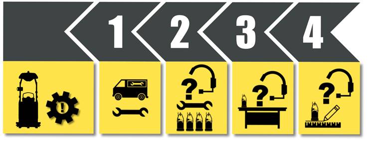
The typical time-to-implementation from an order is approximately 8-10 months. This exact duration depends on the complexity of the solution and the number of Robotic Forklift Trucks that are required. To manage this process, a Project Manager will be assigned to ensure the smooth progress of the activities, from order to acceptance. The following activities take place following an order:
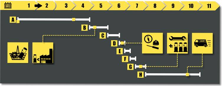
[A] The base forklift trucks are ordered on the factory. The lead-time of the base truck from the factory is typically around 18-20 weeks. This is a little longer than standard due to the preparation required for robotisation.
[B] The base truck is shipped to a dedicated automation facility. Approximately 4 weeks are required for the Automation Preparation.
[C] Factory Acceptance Test preparation consumes 3 weeks. Here, the automation components and software integration of the Robotic Forklift Truck is tested and any initial problems are worked through.
[D] Following a successful Factory Acceptance Test, the Robotic Forklift Truck is shipped to the Customer. Mapping of the application environment and safety testing commences and generally takes 1 week.
[E] Functional testing, adjustment and fine-tuning of the mapping and routes takes a further 1 week.
[F] Ramp up 2 weeks. The ramp-up is when the rest of the Robotic Forklift Truck fleet is connected to the system, the mapping and routes are downloaded and everything is given a shake-down and integration test.
[G] Following go-live, we enter into Hypercare, monitoring the installed system performance and making changes as necessary to promote smooth operation. This is usually around 3 Months.
![]()
Modern navigation systems use a laser, often mounted at a height above pedestrians and other obstructions. The laser detects the position of the reflectors.
The Hyster machine is manually driven round the application, whilst doing this
the truck can record the natural features of the application. after this a
virtual path is added to the layout. The truck can then follow the virtual path
comparing current navigation information to the previous map.